31 Results
View results:
Sort by:

For the stability verification of members using the equivalent member method, it is necessary to define effective or lateral-torsional buckling lengths in order to determine a critical load for stability failure. In this article an RFEM 6-specific function is presented, by which you can assign an eccentricity to the nodal supports and thus influence the determination of the critical bending moment considered in the stability analysis.

The AISC 360-16 steel standard requires stability consideration for a structure as a whole and each of its elements. Various methods for this are available, including direct consideration in the analysis, the effective length method, and the direct analysis method. This article will highlight the important requirements from Ch. C [1] and the direct analysis method to be incorporated in a structural steel model along with the application in RFEM 6.

Defining the appropriate effective length is crucial in obtaining the correct member design capacity. For X-bracing that is connected at the center, engineers often wonder if the full end-to-end length of the member shall be used, or whether using half of the length to where the members are connected is sufficient.This article outlines the recommendations given by the AISC and provides an example on how to specify the effective length of the X-braces in RFEM.

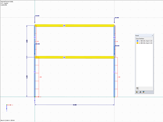
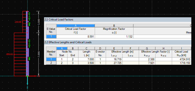
The stability checks for the equivalent member design according to EN 1993-1-1, AISC 360, CSA S16, and other international standards require consideration of the design length (that is, the effective length of the members). In RFEM 6, it is possible to determine the effective length manually by assigning nodal supports and effective length factors or, on the other hand, by importing it from the stability analysis. Both options will be demonstrated in this article by determining the effective length of the framed column in Image 1.

Complex structures are assemblies of structural elements with various properties. However, certain elements can have the same properties in terms of supports, nonlinearities, end modifications, hinges, and so on, as well as design (for example, effective lengths, design supports, reinforcement, service classes, section reductions, and so on). In RFEM 6, these elements can be grouped on the basis of their shared properties and thus can be considered together for both modeling and design.

In CRANEWAY, the action of a rail as "statically effective" or "statically ineffective" is defined under "Rail‑Flange Connection" in the Details dialog box. This setting controls the calculation of the load introduction length according to EN 1993-6, Tab. 5.1.

The RF-STABILITY add-on module determines any critical load factors, effective lengths, and eigenvectors of RFEM models. Stability analyses can be carried out by various eigenvalue methods, the advantages of which depend on the structural system as well as computer configurations.
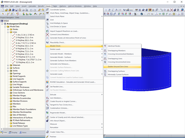
When creating or importing a model, it can happen that lines with a length of zero are created.
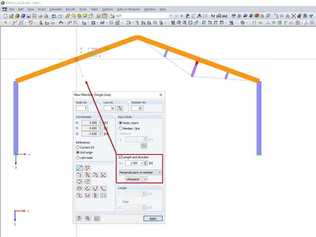
For a frame trussed from below, compression members are to be modelled perpendicular to the inclined beam. The member length and the intersection with the horizontal beam are defined.
In the Formula Editor environment, you can specify any parameters (lengths, force values, and so on) to control load and geometry data in the modeling.

In RF‑/STEEL EC3, you can assign the same input data to several members or sets of members at the same time. The simultaneous assignment of the input data is possible for intermediate supports, effective lengths, nodal supports, member end hinges, and shear panel and rotational restraint.
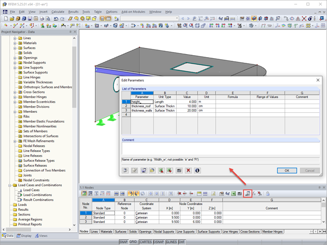
Parameterized entries provide the engineer with an efficiency-increasing tool. This allows entering structural and loading data so that they depend on certain variables. These variables (for example, length, width, live load, and so on) are called parameters.
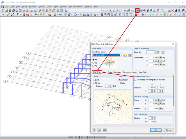
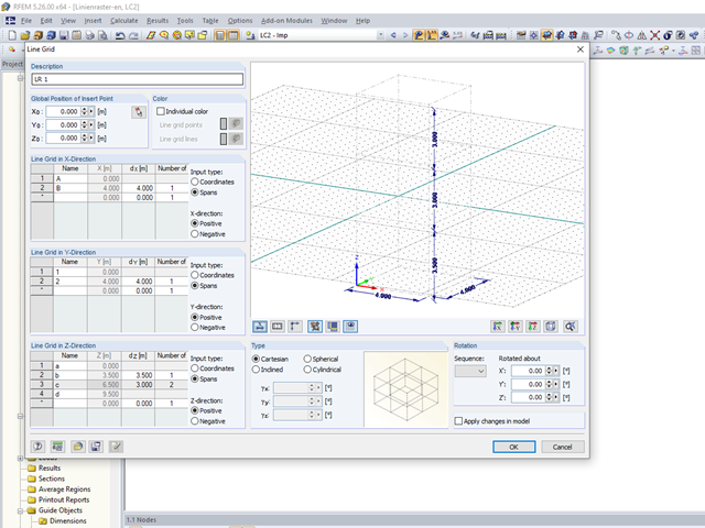
The length of the guidelines corresponds to the dimensions of the set grid and can be adapted by setting the grid.
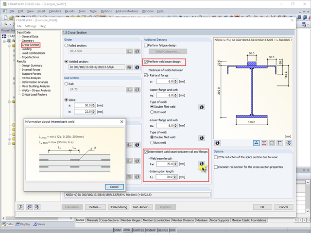
When using interrupted welds between the rail and flange, make sure that the applied weld length does not exceed the length of the rigid load application of the wheel load according to Equation 6.1 in [1].

The RX‑TIMBER stand-alone program offers you the option to optimize the lateral-torsional bracing. With this selection, the program iteratively determines the required minimum length of the lateral-torsional bracing.

When defining the effective slab width of T-beams, RFEM provides the predefined widths that are determined as 1/6 and 1/8 of the member length. A more detailed explanation on these two factors is given below.

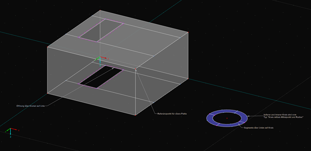
According to Book 631 of the DAfStb (German Committee for Structural Concrete), Chapter 2.4, the structural behavior of ceilings changes if their continuous support by walls is interrupted in areas of openings. Depending on the length of the opening area and the plate thickness, measures are necessary regarding the analysis of the ceiling in the area of the opening.

Reinforced concrete surface design for slabs, plates, and walls is possible in the RF-CONCRETE Surfaces module according to the ACI 318-19 or the CSA A23.3-19 standard. A common approach for slab design is the use of design strips for determining the average one-way internal forces over the width of the strip. This design strip method essentially takes a two-way slab element and applies a simpler one-way approach to determine the required reinforcement needed along the strip length.
With the RF-STABILITY and RSBUCK add-on modules for RFEM and RSTAB, it is possible to perform eigenvalue analyses for member structures in order to determine the effective length factors. The effective length coefficients can then be used for the stability design.

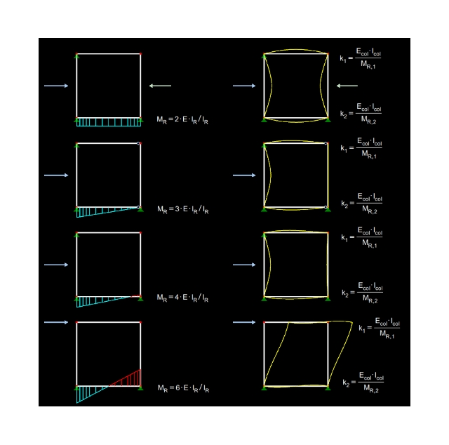
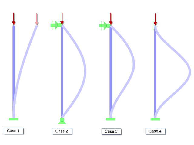
When designing steel columns or steel beams, it is usually necessary to carry out cross-section design and stability analysis. While the cross-section design can usually be performed without giving further details, the stability analysis requires further user-defined entries. To a certain extent, the member is cut out of the structure; therefore, the support conditions have to be specified. This is particularly important when determining the ideal elastic critical moment Mcr. Furthermore, it is necessary to define the correct effective lengths Lcr. These are required for the internal calculation of slenderness ratios.
Effective lengths for columns can be determined automatically with RF-/CONCRETE Columns. This article describes which entries are necessary and how the calculation of the effective lengths is performed.
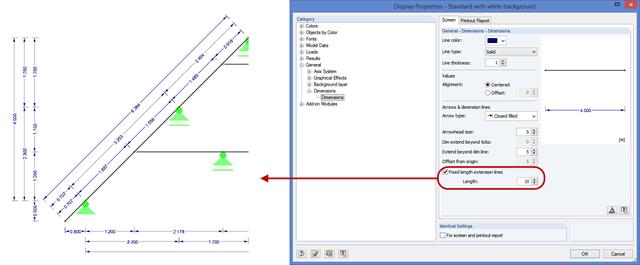
In RFEM and RSTAB, you can now define the guidelines of dimensions with a fixed length. This new option allows you to define dimensions without having the structure covered by the guidelines. This way, dimensioning is clearer. You can activate this option under "Display Properties" → "General" → "Dimensions".
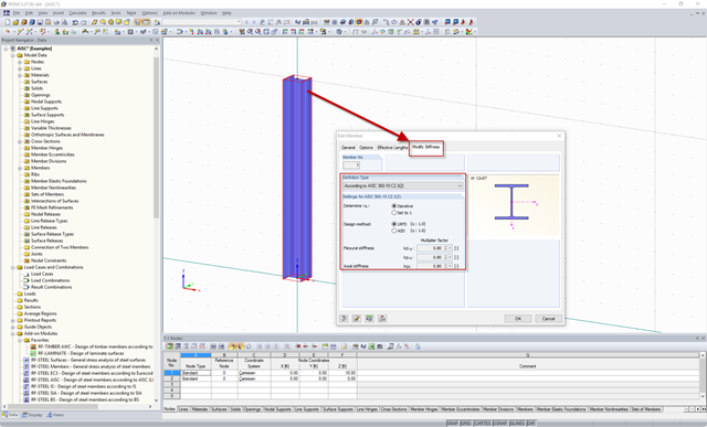
Requirements for the design of structural stability are given in the AISC 360 – 14th Ed. Chapter C. In particular, the direct analysis method provisions, previously located in Appendix 7 of the AISC 360 – 13th Ed., are described in detail. This method is considered an alternative to the effective length method, which in turn eliminates the need for effective length (K) factors other than 1.0.
The RF‑STABILITY and RSBUCK add‑on modules for RFEM and RSTAB allow you to perform eigenvalue analysis for frame structures in order to determine critical load factors, including the buckling modes. Several buckling modes can be determined. They provide information about the model areas bearing stability risks.
When performing the stability analysis of members according to the equivalent member method, considering internal forces according to the linear static analysis, it is very important to determine the governing equivalent member lengths.

In RF‑/TIMBER Pro, it is also possible to define the effective length for lateral-torsional buckling. The effective length for lateral-torsional buckling is then calculated according to EN 1995‑1‑1, Table 6.1. This option is useful especially for non-uniform load introduction.
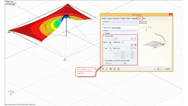
The form-finding process in RFEM seeks an equilibrium state where the defined prestress of membranes and the prestress or length changes of cable elements with boundary reactions are in equilibrium. For this, the program provides the option to define an isotropic or an orthotropic prestress state for membranes.
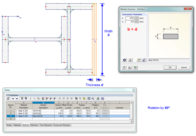
The SHAPE‑THIN cross‑section properties program provides convenient options for graphically setting the section reinforcements. When modeling flat bar extensions, you should note one rule only: The length of the element must be greater than the width.
For recurring elements such as certain structural components or standard parts, you can use the parametrization of a basic model. In the program, the main elements do not represent components but the corresponding node and therefore, they have to be parameterized. For example, a member is not defined by the length, but by the start and end nodes. In this way of modeling, complex formulas may occur especially in the case of three-dimensional structures.
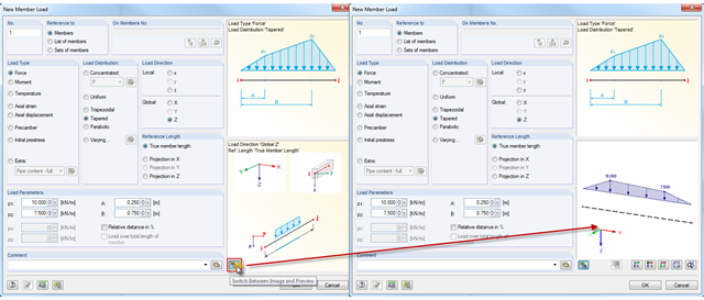
In addition to the load direction and reference length of member loads, it is now possible to display a preview of the loading.